In this post, I will go over instructions to setup and put together the Robot Platform.
First let’s start with components list:
- 1 x Raspberry pi 2 or 3
- 1 x Raspberry pi camera module
- 1 x L298N dual H-bridge module
- 1 x SainSmart 4WD Chassis Aluminum Mobile Robot Platform
- 1 x TriBorg GPIO replicator board
- 1 x Adafruit Mini Pan-Tilt Kit
- 2 x Micro servos
- 1 x Raspberry Pi USB Wifi adapter dongle
- 1 x Toggle switch
- 20 x Jumper wires
- 1 x 12 V rechargeable Battery or 8 AAA batteries
- 1 x Charging socket
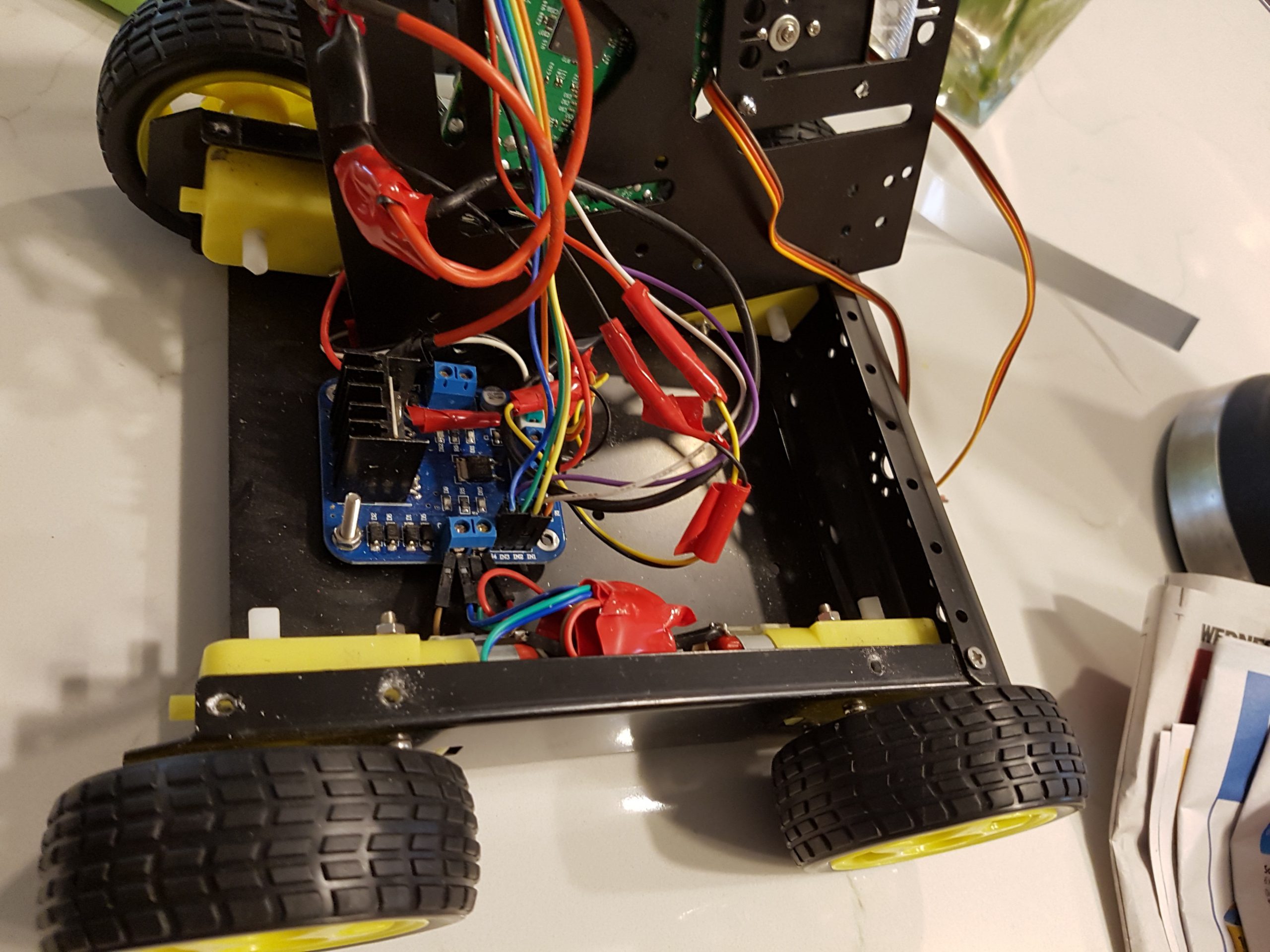
The first step would be mounting 4 DC Motors to 2 side plates and then connecting the lower plate to side plates. Once that is done then you can go ahead and mount the L298N dual H-bridge module to the middle of lower plate.
The next step would be connecting the DC Motors to the L298N dual H-bridge module as it’s showed in following picture:

Each DC motor has two wires for rotating in each direction (One wire for turning the motor clockwise and one wire for rotation in counter clockwise direction). The forward wires of motors on the left side needs to be connected to out1 port of L298N dual H-bridge and the reverse wires are connected to out2 pin. The same goes for the right side of robot and forward wires are connected to out3 port of L298N dual H-bridge and the reverse wires are connected to out4 pin.
Next the rechargeable battery should be mounted at the back of lower plate as it’s showed above. Once the battery secured then you can go ahead and connect the +12v and GND wires of the battery to the VCC and GND inputs of L298N dual H-bridge module. A power switch and a charging connection needs to be used as it’s shown below in case you would like to use a reachable battery.

The GND and +5V of L298N dual H-bridge module need to be connected to pin #6 (GND) and pin #2 (+5V) of raspberry pi. I decided to use a TriBorg GPIO replicator board as it gives me more power pins and it replicates GPIOs.
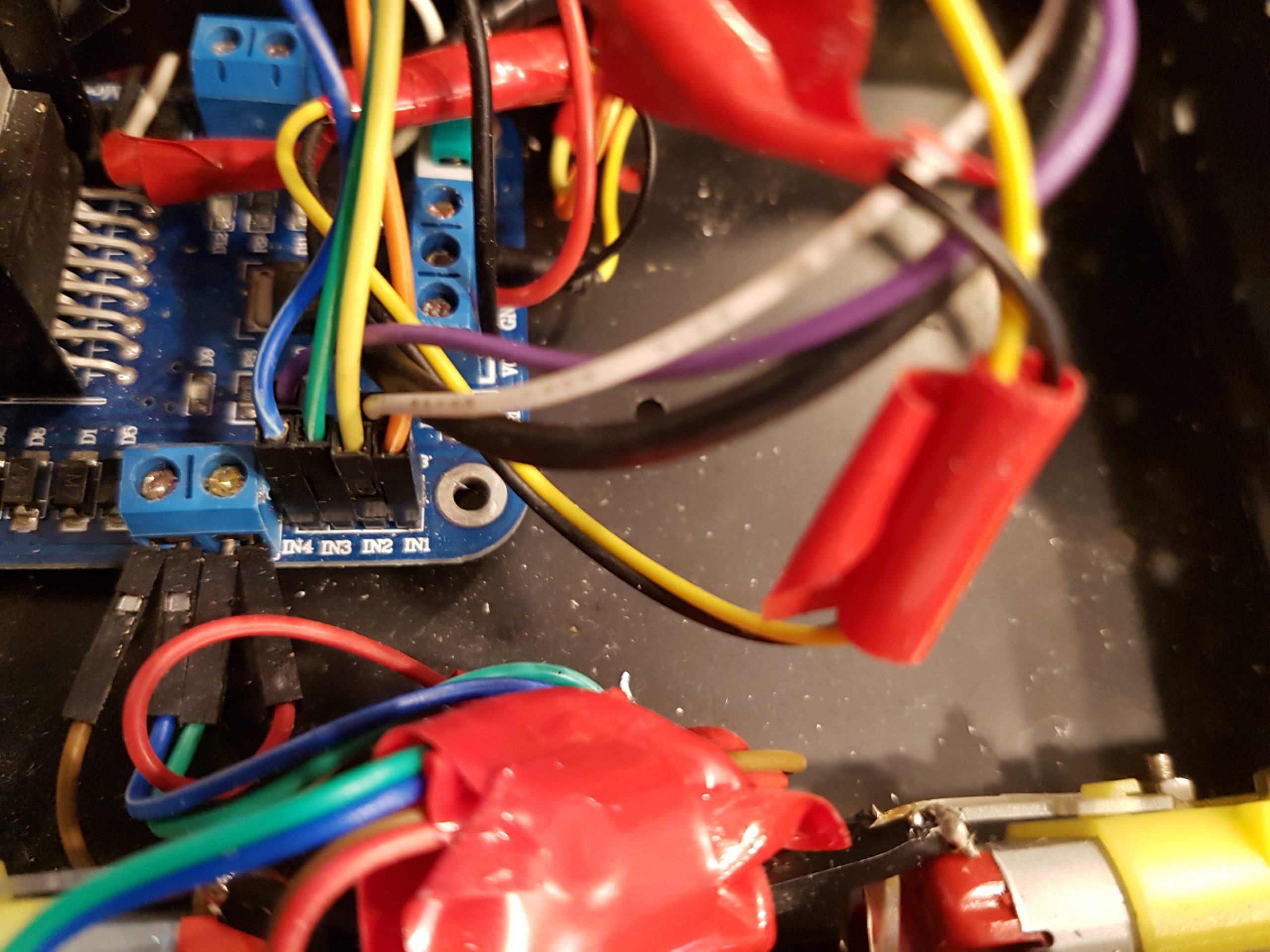
The next step would be connecting the input pins of L298N dual H-bridge module to the GPIO’s of raspberry pi in following order:
- IN1 to GPIO pin # 7 ( Orange)
- IN2 to GPIO pin # 11 ( Yellow)
- IN3 to GPIO pin # 13 ( Green )
- IN4 to GPIO pin # 15 ( Blue )
- ENA to GPIO pin # 16 ( Purple )
- ENB to GPIO pin # 16 ( White )


You will need to look at raspberry pi pinout map to make sure pins are connected correctly.

ENA and ENB pins are used to enable and disable Outputs of L298N dual H-bridge.

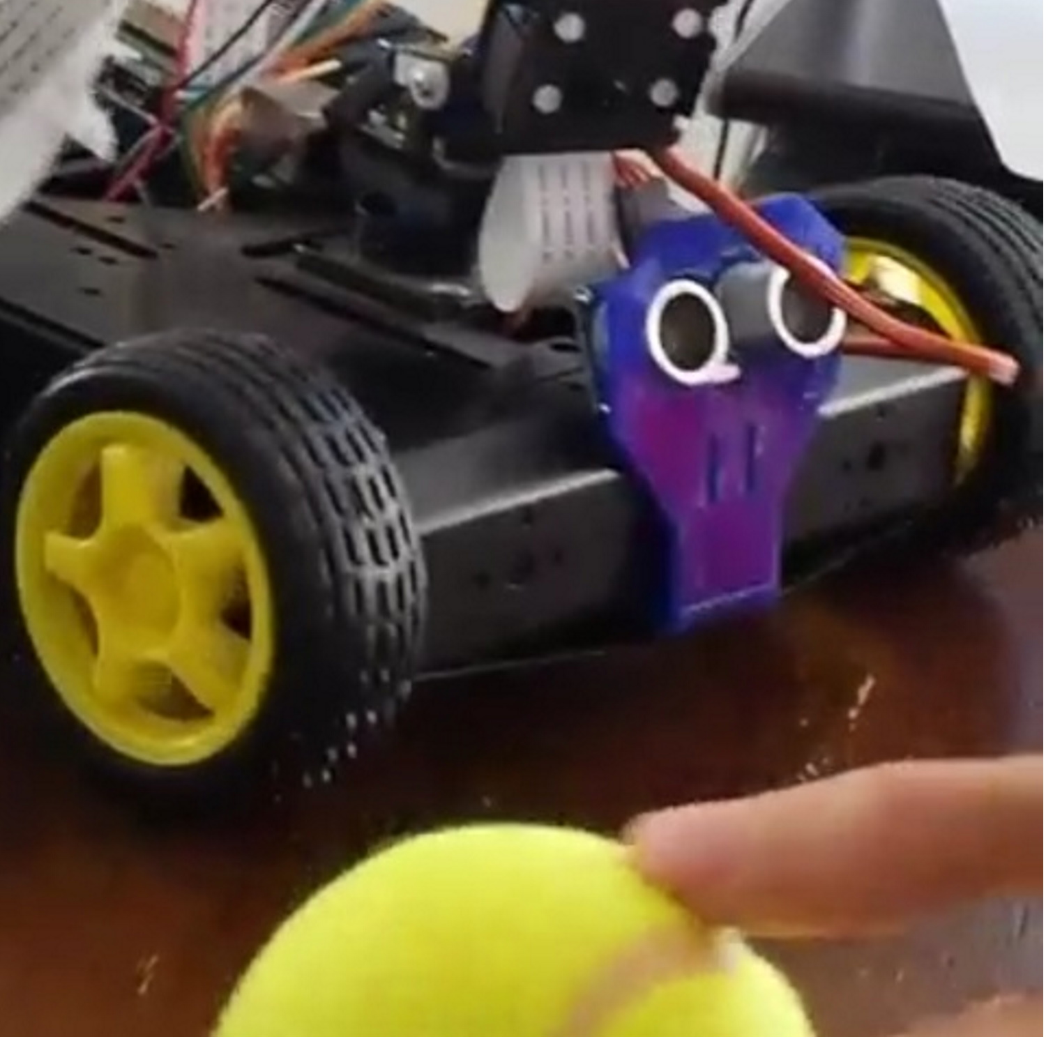
Now we can go ahead and mount the top plate, front plate and back plate of Robot Platform.
This covers the setup of Robot Platform and you can visit Sainsmart website for more details on setting up the Robot Platform.
In next post, I will go over the driver code and explain how to move the robot using a wireless keyboard.